PDF/VT Transparency Guide
Boris Aronshtam
VDP Tech
www.vdptech.com
©2008-2009 VDP Tech Incorporated
Last
Revision: Jan 2, 2009
Revision History
|
Date
|
Changes
|
|
01/01/2009
|
Original Version
|
|
10/18/2009
|
Added SoftMask
clipping section
|
There are numerous discussions related to defining the most adequate
transparency model that combines the power and simplicity. Obviously, the
ultimate PDF transparency guide is Adobe PDF Reference that can be found at http://www.adobe.com/devnet/pdf.
Unfortunately, as the experience shows, it is not that easy to understand all
the numerous PDF transparency issues from this reference text. Moreover, some
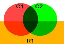
information is confusing. For example, Plate 17 of the reference that shows the
difference between isolated and non-isolated groups is misleading. It led many
PDF/VT participants to believe that isolated PDF transparency groups always
obscure the background. Though PDF/VT and PPML standard groups are already beyond
this basic understanding, nevertheless, there are still multiple PDF
Transparency issues that are still confusing to even the most educated
participants.
The purpose of this book is to elaborate on the complex transparency issues.
Thus you can consider this book as a companion to Transparency chapter of PDF
Reference Manual.
Whenever it is possible, we will try to illustrate the points with
straightforward hand-made PDF and PDF/VT examples. You are welcome to use all
the examples freely, while paying respect to the copyright and credit lines and
keeping them intact.
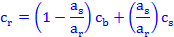
Let us start with PDF Transparency Blending Formula. Let us use the
canonical representation of this formula.
ar
= 1 - (1-ab)(1-as)
arcr = (1-as)abcb + (1-ab)ascs + abasB(cb,cs)
According to PDF Transparency Model, an object in each point
has Color (c) and Opacity (a).
The formula calculates the resulting opacity (ar) and the
resulting color (cr),
according to
-
Source color (cs) and source
opacity (as)
-
Background color (cb) and background opacity (ab)
-
Blending function (B).
This fairly complex formula has a number of fairly simple
cases.
Completely opaque objects defined as having opacity=1. For
such object the formula is simplified to:
ar = 1
cr = B(cb,cs)
Though the
resulting formula is extremely simple, the result is far from being trivial. It
says that even the completely opaque objects interact with each-other while
blending. Or in other words, there are no completely opaque objects.
Completely transparent background has ab=0. For such
object the formula is simplified to:
ar = as
cr = cs
According to this formula, placing an object on a completely
transparent background does not change the appearance of the object.
Normal Blend Mode is the most intuitive blend mode (probably
the only intuitive mode). It is defined as
B(cb,cs)
= cs;
For this mode:
PageBackground.pdf is the simplest pdf example. It can be used as the
template for the hand created pdf files.
The white page background has rgb=[1 1 1]. But what is the page background
opacity ab?
Is it 0 (completely transparent) or 1 (completely opaque)? The PageBackground.pdf test
provides the answer to this question: the page background is completely
opaque.
Let us use the above formulas for the completely transparent and completely
opaque backgrounds:
completely transparent: (ab=0); ar=as; cr=cs
completely opaque: (ab=1); ar=1; cr= (1-as) + asB(1,cs)
In case of the transparent background, the resulting color cr
is unaffected by Cb
and the blending function. The source color just transparently passes
through the background. In case of the opaque background, the resulting color cr
is affected by cb
and the blending function in the non-trivial way. For simplicity let us
use BM=Normal. In this case the formula is simplified:
B(cb,cs) = cs; cr= 1-as(1-cs)
The example draws 3 red (rgb=[1 0 0]) rectangles. Each rectangle has a
different opacity as shown in the table together with the resulting color
values:
|
R1
|
R2
|
R3
|
R4
|
|
a
|
1.0
|
0.5
|
0.2
|
0.0
|
|
r
|
1.0
|
1.0
|
1.0
|
1.0
|
|
g
|
0.0
|
0.5
|
0.8
|
1.0
|
|
b
|
0.0
|
0.5
|
0.8
|
1.0
|
This exactly corresponds to the resulting PDF page as shown:
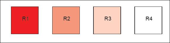
So the conclusion of this
example is that page background is completely opaque.
3.2 Blending with Page Background
But as Dr. Paul Jones has pointed out, this is not the end of the story. It
is wrong to treat the page background as a separate color. Page background is
not a color, but the unmarked space. There is a cardinal difference between
this unmarked space and the marked white color with opacity=1. This is
illustrated by PageBackgroundBlending.pdf:
As one can see, blending with the background ignores the blend mode, and is
equivalent to blending with BM=Normal against the opaque white color.
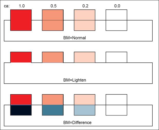
BlendModes_rgb.pdf and BlendModes_cmyk.pdf shows all the PDF Transparency blend modes defined in
the PDF spec. As you can see, the result of blending is significantly affected
by the blending color space.
|
RGB
Blending Color Space
|
CMYK
Blending Color Space
|
|
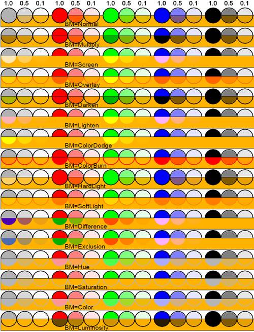
|
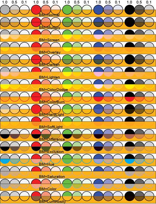
|
For each blend mode there are 5 group of circles: gray, red, green, blue,
and black. Each group shows exactly the same circle with 3 opacities: 1.0, 0.5,
and 0.1. Though the example is very simple, it reiterates a non-trivial
conclusion:
Even completely opaque objects (ca=1) interact with the background. This is
completely counterintuitive. Think about it for a moment: holding in your hand
a brick, you cannot see anything behind it -- whatever light you shine through
it. Only Normal opaque blend mode does not interact with the background - thus
it is the only intuitive blendmode.
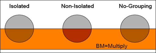
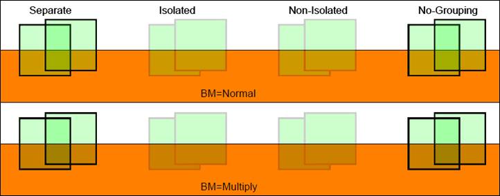
In this chapter we will shows the difference between isolated transparency grouping, non-isolated transparency grouping, and no-grouping.
Isolation_rgb.pdf illustrates the
difference between pdf isolated and non-isolated transparency groups:
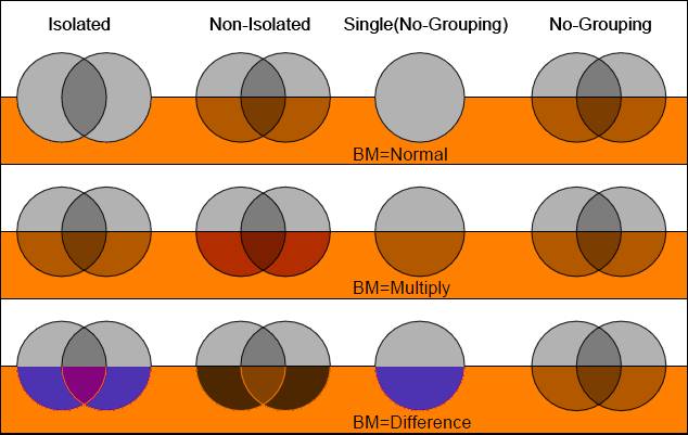
Each row contains exactly the same 2 gray circles. These 2 gray circles are
blended together in BM=Multiply and combined into 3 individual XObjects:
Isolated, Non-Isolated, No-Grouping. For each blend mode it shows the following
4 columns:
- Isolated transparency
group XObject blended with the orange background using the specified
blendmode.
- Non-Isolated transparency
group XObject blended with the orange background using the specified
blendmode.
- The single gray circle from
the group blended with the orange background using the specified
blendmode.
- Non-grouped XObject.
The visual
result can be verified with calculations and compared against the values
reported by Acrobat9 (Advanced:PrintProduction:OutputPreview). The following object RGB values are used:
Gray Circle: [0.7 0.7 0.7]
Orange Rect: [1.0 0.5 0.0]
No-grouping case is the simplest case. It is equivalent to
the placement of the individual circles in the group onto the background. The
circles in the group are blended with the orange background in BM=Multiply.
This BM overrides the external blend mode (Normal or Difference), thus
resulting to the same result for all the blend modes.
|
|
Calculations
|
Result
|
|
Orange Rect
|
|
[1.00
0.50 0.00]
|
|
Gray Circle
|
|
[0.70
0.70 0.70]
|
|
Single Intersection
|
[0.7*1.0
0.70*0.5 0.7*0.0]
|
[0.70 0.35 0.00]
|
|
Double Intersection
|
[0.7*0.7
0.35*0.7 0.0*0.7]
|
[0.49 0.24 0.00]
|
The circles are blended together (BM=Multiply) in complete isolation from
the background and the result is blended with the background. This is fairly
intuitive and can be easily verified and understood using vdptech TransparencyViewer.
According to the "PDF Reference Manual", the non-isolated
transparency groups are somewhat even simpler than isolated groups. They are
composited with the background as if no grouping occurs.
Indeed, the result of BM=Normal at the pdf file (1st row) can be derived as:
- Combine the 1st circle
with the orange background in BM=Multiply.
- Combine the 2nd circle
with the orange background in BM=Multiply.
- Combine the 1+2 together in
BM=Normal.
Unfortunately, none of the other blend modes can be explained in the same
manner for the BM=Multiply (2nd row). To simplify isolation vs. non-isolation
matter even further let us examine IsolationSimple.pdf,
where the issue of non-isolation is simplified and taken to the extreme by
limiting the group to just one circle. As you can see, the bottom part of the
non-isolated circle differs from the isolated circle. Why?
To answer
this question one must carefully examine “Group Compositing Computations” presented in PDF
Reference. The calculations must take
into account 1) the orange background when the group is calculated and 2) the
orange background when the group is applied. All the calculations are
significantly simplified by the fact that all our opacities = 1. Here are the
calculations for non-isolated blending:
|
|
|
Calculations
|
Result
|
|
R
|
Orange Rect
|
|
[1.00
0.50 0.00]
|
|
C
|
Gray Circle
|
|
[0.70
0.70 0.70]
|
|
G
|
Group Calculation
|
C
Mult R = [0.70*1 0.70*0.5 0.7*0]
|
[0.70 0.35 0.00]
|
|
F
|
Final Result
|
G
Mult R = [0.70*1 0.35*0.5 0.0*0]
|
[0.70 0.18 0.00]
|
The
calculated result precisely matches the result reported by Acrobat9. The
conclusion of this result is that the orange background is applied twice. Group
Compositing Computations fail to compensate for the orange background when the non-isolated
group is blended with the background.
This subject causes and will continue to cause the heated discussions in
PDF/VT and PPML standard committees. Despite the multiple requests, no one yet explained the non-isolated transparency group benefits.
Looking at Adobe InDesign documentation and Adobe "A
Designer Guide to Transparency" does not help, but rather further
confuses the subject - all the examples show Isolated Transparency as opaque
and completely covering the background. Considering all the non-intuitiveness
and the complexity of the matter and the absence of practical examples in Adobe
literature, vdptech concludes
that non-isolated transparency groups do not provide any value to the
users. We would also suggest removing support for non-isolated groups
in the next version of PDF.
This chapter shows how to create pdf radial shading and pdf soft masks built
out of radial shades.
This section is a small diversion from our main subject of pdf transparency.
But it is useful to have this sample handy for using in PDF Soft Masks in the
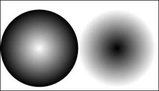
following chapters. RadialShading.pdf
shows how to implement radial shading in PDF.
SoftMask.pdf is
a simple example that shows PDF SoftMask usage. It
defines Radial1 XObject as a red square with
SoftMask defined as Radial Shade. This Radial1
XObject is placed twice onto the cyan background.
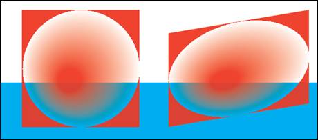
It is important to understand that a SoftMask is not a raster objects, but
just an attribute of pdf graphics state (similar to opacity, current color, or
clipping path) used to create a raster object (like Radial1 XObject in the
example).
As the previous example clearly shows, unmarked
pixels (the pixels beyond the circle) do not contribute to the soft mask. This
is why the “undesired” red square is visible. To clip this “undesired” square,
the square (i.e. the bounding-box) needs to be erased by painting it white,
before painting the radial shade.
SoftMask-Clipped.pdf compares the unmarked
bounding-box on the left, to the marked bounding-box on the right. The bounding
box on the right is “erased” with rgb=[0 .1 0], which results in pale ghost red
square.
7
PDF/VT
Encapsulated Form XObjects
This chapter deals only with PDF Form XObjects. Other types of XObjects
(Image XObjects and Reference XObjects) are not discussed here.
PDF/VT committee is currently in the process of defining PDF
Encapsulated XObjects. This is a kind of an object that can be rendered once
and placed multiple times - similar to Reusable Occurrences in PPML. Therefore,
the predictability of PDF XObject is required.
A general PDF Form XObject is like a template that depends on the parameters
specified at the XObject invocation time. Thus the same XObject may visually
appear completely different, when invoked from the different contexts. For
example, if the XObject does not define its own color, the external color is
used. Thus, depending on the page graphics state, the same XObject can appear
red or green. The current thinking in PDF/VT is to encapsulate all the required
graphics attributes within the XObject, so it does not depend on the
external context. The resulting Encapsulated XObject is only subject to CTM
transformation at the invocation time (so it only can appear translated,
zoomed, or skewed on the page).
Our conclusion is that the encapsulation can only be achieved with
Isolated Transparency Grouping. This conclusion is demonstrated by the
following examples.
Encapsulation.pdf shows the reaction of
different types of Form XObjects on the external graphics state.
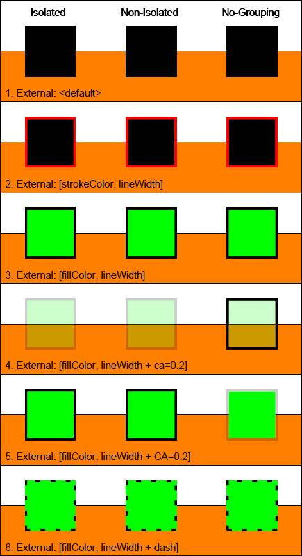
The test uses 3 squares. Each is defined as XObject that draws a square, with
no explicit attributes (no explicit fill-color, no explicit stroke-color, no
explicit opacity, etc.). The reason they all look different is only
because the graphics state (gs) on the page changes and affects the visual
appearance. Let us go row by row:
- No explicit gs is set on the
page. Color is undefined – black.
- Stroke-color and line-width
are defined externally. All squares inherit these values.
- Fill-color and line-width are
defined externally (for rows 3 to 6). All squares inherit these values.
- Fill opacity (ca) is defined.
It affects the objects differently:
-
Grouped objects (isolated and non-isolated): ca is
applied to the object as a whole (fill and stroke are treated the same)
-
Ungrouped object: ca is inherited.
- Stroke opacity (CA) is
defined.
-
Grouped objects (isolated and non-isolated): CA is
ignored.
-
Ungrouped object: inherited.
- Dash is defined. All squares
inherit this value.
The test obviously can be expanded to check for multiple other attributes
(linejoin, miterlimit, etc.). But the picture is quite obvious:
Non-Grouped Objects
A non-grouped object behaves as inline code, inserted at the invocation
time. If it defines some attributes, they are used. Otherwise, the external
attributes are applied. As shown by Isolation.pdf
example above, even the external blend mode is ignored. This makes non-grouped objects unsuitable for the encapsulation.
Grouped Objects
Unfortunately, a grouped object is not encapsulated by default: if some
attributes are undefined, they are inherited from the external context. These
attributes include most of the boring gs attributes: color, line
width, line join, miter limit, line cap, dash pattern, etc.
But all the attributes related to transparency have implicit default values.
Moreover, these attributes interact with the external gs (combined):
|
Parameter
|
Default
Value
|
Interaction
with External Graphics State
|
|
Fill Opacity: ca
|
1.0
|
External ca is applied to the entire object
|
|
Stroke Opacity: CA
|
1.0
|
External CA is ignored
|
|
SoftMask
|
None
|
External SoftMask is applied to the entire object
|
|
BlendMode
|
Normal
|
External BlendMode is applied to the entire object
|
As we saw in the previous section, some gs parameters (like
Color and Dash Pattern) are clearly inherited from the external context. But
how do we know that the transparency parameters have predefined default values
and not just inherited from the external context?
UndefinedOpacity.pdf
proves that Fill Opacity (ca) is not inherited.
Similar to the previous example, the test draws squares. Each is defined as
XObject with no explicit attributes whatsoever. The appearance of the
squares is manipulated from the external context. The external opacity is set
to the low value of ca=0.2,
so the effect is easily visible. The squares are blended with each-other in
Normal mode.
1. Drawing
Non-Grouping squares is equivalent
to drawing 2 Separate squares. Each
square inherits the external ca value when blending with the background. The
intersection of the squares darkens as the result of this blending.
2. The
grouped squares (Isolated and Non-Isolated) are blended together with
the default opacity of ca=1.
At their intersection the top square simply replaces the bottom square. Then
the resulting group is blended with the background with ca=0.2.
SoftMask-Interaction.pdf
shows
that the external SoftMask is not ignored, but applied to the entire Grouped XObject.

The example is derived from SoftMask.pdf.
For simplicity the blue background is removed. Radial1
is defined as Isolated Group XObject and placed twice onto the page (left and
right). Radial1 on the right is exactly the same as
in the previous example. Radial1 on the left is
placed onto the page when the same external SoftMask is defined in the page
graphics state (external SoftMask). As you can see, this results in steeper
white gain when moving from the center: effectively we have the SoftMask
squared.
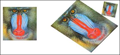
A PDF Reference XObjects refer to a page of another PDF file. This enables
one PDF document to import content from another. The document in which the
reference occurs is called the containing document; the one whose
content is being imported is called the target document.
Note that there is no mechanism for the containing document to
address a single XObject in the target document. An individual XObject
in the target document can be addressed only by target document enclosing
it into a page.
An excellent discussion on the subject can be found at Adobe
PDF Reference XObject Blog, including a number of good examples. Though the
Reference XObjects were defined since PDF 1.4, this is a very fresh
subject: Adobe Acrobat before 9.0 did not support Reference XObjects.
Starting with 9.0, the PDF Reference XObjects are supported by all Acrobat
flavors (Reader, Standard, and Professional). The PDF Reference XObjects in
Acrobat are disabled by default. To enable them please refer to Adobe
PDF Reference XObject Blog. In a snapshot, to enable PDF Reference XObjects
support:
- Reference XObjects must be
enabled in Page Display preferences.
- The location of target
documents must be added to the privileged locations in Security (Enhanced)
preferences. Note that each directory must be pedantically specified
separately: specifying the parent directory is not sufficient.
There is no clarity at this time if PDF Reference XObjects will be used in
PDF/VT as a viable way of referring to the external content (equivalent for
example to PPML's ExternalDataArray). The purpose of the following sections is
to show the pdf transparency behavior of Reference XObjects. In the spirit
of the thread we will keep the examples small and readable. Because of the PDF
security issues described above, the examples in this section are not
clickable: the pdf files must be downloaded to the Acrobat privileged
directories.
Let us show a simple test that demonstrates the use of Reference XObjects. Ref-SimpleTest.pdf refers to target
document Ref-Target.pdf (you are welcome
to substitute this target file for any of your files). Before running the
example you need to place the 2 files into your privileged
directory specified in Acrobat app.
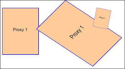
And if despite all our warnings you have not created your privileged
directory, your target file will not be used, the image will be replaced
by the alternative proxy content, and you will get the following result:
Creating Reference XObjects
is simple. It is created as a regular Form XObject containing /Ref entry:
21 0 obj
<<
/BBox [0 0 612 792]
/FormType 1
/Subtype /Form
/Type /XObject
/Ref <</Page 0 /F
(Ref-Target.pdf)>>
>>
stream
proxy content % executed when target is not found
endstream
endobj
Now, when we are comfortable with creating Reference
XObjects that refer to pages in external files, let us experiment and see the
best way to encapsulate the Reference XObjects. Please use the following files
and copy them to your privileged directory:
Ref-EncapsulationTest.pdf - the test that refers to Ref-EncapsulationTarget-Valid.pdf target.
Ref-EncapsulationTarget.pdf - the handmade target file.
Ref-EncapsulationTarget-Valid.pdf - the “valid” pdf file obtained by opening
and closing the handmade
target file Ref-EncapsulationTarget.pdf.
Ref-EncapsulationTarget.pdf contains 2 pages named Target#1 and Target#2:
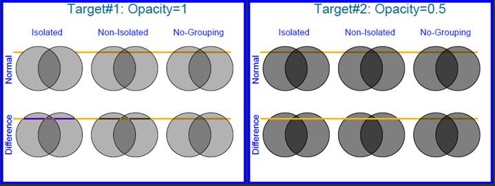
Both pages contain our typical circles blended
together in Multiply blend mode. Target#1 circles are gray circles with ca=1. Target#2 circles are black circles with
ca=0.5. A golden thin band is placed as a background (under the circles). This
band is very handy in observing the interesting behaviors. Let us list some of
the observations.
·
Ignoring for a moment the interaction with the
golden band, all the circle groups look exactly the same. That is: grouping, isolation,
and external blending mode are ignored when blending with empty background (see
Blending with Page Background).
·
Target#1, Normal blend-mode:
o
Isolated group (as expected) obscure the golden
band.
o
Non-Isolated group interacts with the band; and
though the circles are opaque, the band is seeing through.
·
The golden band looks differently when
interacting with different circles.
Ref-EncapsulationTest.pdf
contains 2 pages. The 1st
page refers to Target#1 (opaque gray circles), the 2nd page refers
to Target#2 (semi-transparent black circles). Each page has 3 columns:
1.
Isolated
RefObject. Reference XObjects are declared as Isolated Transparency Group.
2.
Non-Isolated
RefObject. Reference XObject are declared as Non-Isolated Transparency
Group.
3.
Non-Grouped
RefObject. Reference XObjects are not grouped.
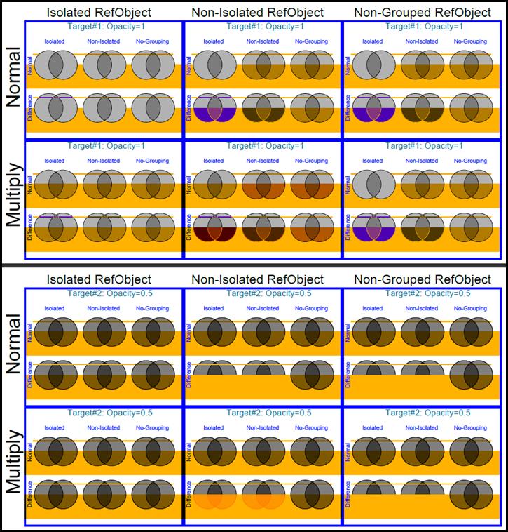
Having the visual result, let us go through the observations for each RefObject
grouping:
Isolated RefObject Grouping
·
The visual appearance of target pages is preserved.
·
The object opacities are preserved.
·
Target Page blend mode is ignored.
·
Target Page raster can be captured and used
multiple times
Non-Isolated Grouping
·
The visual appearance of target pages is not
preserved.
·
The object opacities are preserved.
·
Target Page blend mode is preserved, thus
further complicating the visual appearance.
·
Target Page raster cannot be captured for
multiple reuse
Non-Grouping
·
The visual appearance of target pages is not
preserved.
·
The object opacities are preserved.
·
Target Page blend mode is preserved, thus
further complicating the visual appearance.
·
Target Page raster cannot be captured for
multiple reuse
The explanation of the special effects of Non-Isolation and Non-Grouping is left
as an exercise to the readerJ
The target pages can be nicely encapsulated by declaring the
Reference XObjects referring to them as Isolated Transparency Groups. Not only is
this a nice way of encapsulating, but the only one.
This conclusion can be combined with the conclusion of PDF/VT Encapsulated Form XObjects chapter:
Encapsulation can only be achieved with Isolated Transparency Grouping.